Ultrasound
Physics in Medical Imaging
Basic Ultrasound Physics
Ultra-sound
- ultra - "on the farside of, beyond"
- sound - "vibrations transmitted through an elastic solid, liquid, or gas"

Main Physical Phenonmena
- Speed of sound
- Scatter
- Attenuation
Speed of sound
$$c = f \lambda$$
- $c$ - speed of sound
- $f$ - frequency
- $\lambda$ - wavelength

Speed of sound
$$c = \sqrt{\frac{K}{\rho}}$$
- $c$ - speed of sound
- $K$ - bulk modulus (pressure required to compress)
- $\rho$ - density
Acoustic impedance
$$Z = \frac{p}{u} = \rho c$$
- $Z$ - acoustic impedance
- $p$ - acoustic pressure
- $u$ - wave particle velocity
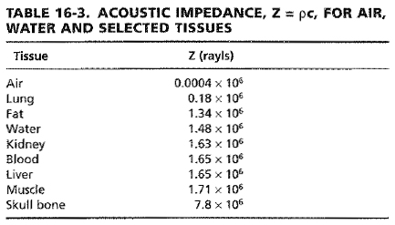
Changes in wave propagation are caused by acoustic impedance gradients.

The behavior of the change depends on the size of the acoustic impedance variation relative to the incident wavelength.

When the structure is much larger than the wavelength, a specular reflection occurs. This happens organ boundaries.
When the structure is much smaller the wavelength, scattering occurs. This occurs in parenchyma where cells are relatively uniform. It manifests as speckle in ultrasound images.
Much content in an ultrasound image are from structures with a size somewhere in between.
Specular reflection
For a plane wave,$$\frac{P_{-1}}{P_{+1}} = \left( \frac{Z_2 - Z_1}{Z_2 + Z_1} \right)$$
- $P_{-1}$ - reflected wave amplitude
- $P_{+1}$ - incident wave amplitude
- $Z_1$ - first material acoustic impedance
- $Z_2$ - second material acoustic impedance
$$\frac{P_{+2}}{P_{+1}} = \left( \frac{2 Z_2}{Z_2 + Z_1} \right)$$
- $P_{+2}$ - transmitted wave amplitude

Refraction
Refraction also occurs for large structures according to Snell's Law, $$\frac{\sin \theta_i}{\sin \theta_t} = \frac{\lambda_1}{\lambda_2} = \frac{c_1}{c_2}$$

Scatter
Scattering is angle dependent.

And frequency dependent.

Attenuation
Attenuation is the fractional loss in plane wave intensity per unit distance travelled.
$$P(x + \Delta x) = P(x) e^{- \alpha \Delta x}$$- $P(x + \Delta x)$ - pressure after propagating $\Delta x$ distance
- $\alpha$ - attenuation coefficient
Attenuation
Two causes of attenuation
- scattering - some of the wave is scattered as it propagates. ~10% of the attenuation coefficient.
- absorption - the wave energy is converted to thermal energy. ~90% of the attenuation coefficient.
Attenuation
The attenuation coefficient is of expressed in units of Nepers per centimeter per Megahertz (Np / cm / MHz) or Decibels per centimeter per Megahertz (dB / cm / MHz) because an approximate linear dependency with frequency is observed for soft tissues.

Medical Image Formation
Ultrasound Image

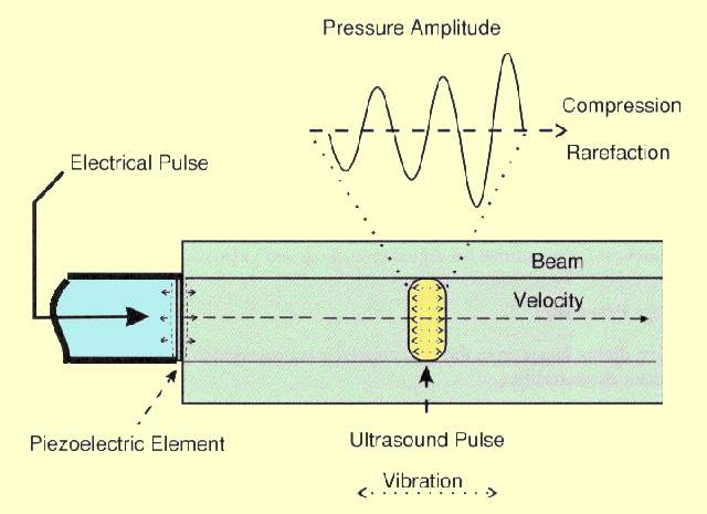
Transducer
The transducer is usually a piezoelectric crystal that both transmits and receives the pressure waves.
Transducer
Excitation of the crystal with electricity causes it to vibrate. When pressure wave return to the crystal, its movement creates the electrical signal that is recorded.
Transducer
The transducer has a natural center frequency and bandwidth that result from geometry and mechanical material properties.

Pulse-echo
The transducer is excited with a short-time pulse.
After transmitting, the transducer is immediately put into receive mode to listen for backscattered waves as the pulse propagates.
This is called pulse-echo imaging.
Pulse-echo
The depth of the received echo signal is determined with the range equation $$d = \frac{c t}{2}$$
- $d$ - depth
- $t$ - pulse-echo transmit time
- $c$ - speed of sound, assumed constant 1540 m/s
Beam
The insonified region in roughly confined to a column or beam.


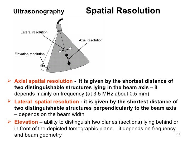
Beam
Directions are defined relative to pulse propagation.
- axial - axis of the beam
- lateral - orthogonal to the axial direction, in the imaging plane
- elevational - orthogonal to the axial direction, out of the imaging plane

Beam
Highly anisotropic resolution.
axial >> lateral > elevational
Time Gain Compensation (TGC)
Beam intensity variations and attenuation cause average signal strength to vary with depth.
A variable gain is applied with depth - time gain compensation (TGC).


Transducer Types
Single element

Array
Single element
Pulse-echo lines are collected as it is mechanically rotated to form an image.
Array
Multiple elements are arranged in a line. By varying the intensity and timing of the element excitation, the beam location and intensity is controlled.

Array
The element yellow dot position is the equivalent effect of pulse time delays.
RF Data
The signal from a single element transducer or the summed signal from all the elements of an array transducer is called the raw RF (radio-frequency) data.
B-mode
The envelope of the RF data forms the B-mode (brightness-mode) intensity image.

Ultrasound Tissue Characterization
B-mode Content
The B-mode intensity image is a mix of- Transducer insonification characteristics
- Tissue acoustic characteristics
- Plentiful artifacts
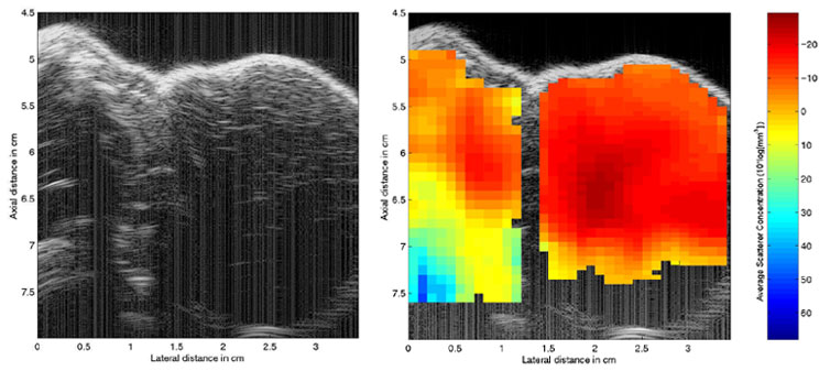
Ultrasound Tissue Characterization
Ultrasound tissue characterization techniques attempt to reduce insonification characteristics and present tissue properties in the image.Parametric Images
Ultrasound tissue characterization images are parametric images derived from acoustic properties, such as- Speed of sound
- Attenuation coefficient
- Parameters related to the frequency-dependent backscatter coefficient
Backscatter coefficient estimation
Normalize the local speckle spectrum by the RF data from a perfect planar reflector or uniform tissue-mimicking phantom to remove transducer properties.
Spectral characteristics
Fix parametric models of scatterer size, e.g., or measure slope, intercept, integral to normalized spectrum.